Guide
Rooftop Unit Thermostat Considerations
What to verify about packaged rooftop equipment before selecting a thermostat or connected control.
Updated
Packaged rooftop units (RTUs) vary widely in control voltage, terminal conventions, staging, and ventilation strategy. Two units that look identical on the curb can require different controls, so confirm the electrical and sequencing details of the actual equipment before selecting a thermostat. This guide explains what each detail means and why it drives the control decision.
1. Confirm the unit model and heating type
Start from the RTU's nameplate model and serial numbers, then pull the current manufacturer installation manual for that specific model. The single most important thing the manual tells you is the heating type, because it changes the terminal set the control must drive:
- Gas/electric (conventional): heat is a call on
W1/W2; cooling isY1/Y2. - Heat pump: there is no
W1for compressor heat - the reversing valve is energized onO(energize-on-cool) orB(energize-on-heat), staging runs throughY1/Y2, and auxiliary/emergency heat lands onW2/AUX/E. - Dual-fuel (heat pump + gas): requires a control that supports changeover logic and a fossil-fuel lockout.
A conventional thermostat and a heat-pump thermostat are not interchangeable even at the same voltage, so this determination comes first.
2. Verify control voltage and transformer capacity
Nearly all commercial RTU low-voltage control circuits are 24 VAC nominal, typically measured ~24-28 VAC at the terminal block under no load (the practical working range is roughly 18-30 VAC). Confirm before assuming:
- Measure between
R(24 VAC hot) andC(common) with a multimeter set to AC volts. - Check the transformer VA rating in the unit documentation. Connected and Wi-Fi thermostats draw continuous current from
C; a marginal transformer can cause resets or dropouts. - Line-voltage (120/240 VAC) and millivolt systems exist but are uncommon on packaged commercial RTUs - if you measure either, stop and treat it as a different control class.
If the equipment provides a dedicated C terminal, plan to land the common; most connected and building-network thermostats require it for reliable power.
3. Map the terminals to the required stages
Record every terminal the unit actually uses and match it to the control's capability. A typical multi-stage gas/electric RTU exposes:
| Terminal | Function | Notes |
|---|---|---|
R / Rc / Rh |
24 VAC power (cooling / heating) | Jumper Rc-Rh only if the unit uses a single transformer |
C |
24 VAC common | Needed for powered / connected controls |
W1 / W2 |
Heat stage 1 / stage 2 | Heat pump uses W2/AUX for backup heat |
Y1 / Y2 |
Cool (compressor) stage 1 / stage 2 | Also compressor stages on a heat pump |
G |
Indoor (supply) fan | Often energized with any call in commercial units |
O / B |
Reversing valve (heat pump) | O energize-on-cool, B energize-on-heat |
The control you select must support the same number of heat and cool stages the RTU provides. Pairing a single-stage thermostat with a two-stage unit strands second-stage capacity; the reverse can short-cycle the compressor.
4. Account for the economizer and ventilation interface
Many commercial RTUs include an economizer or a dedicated outdoor-air/ventilation package. This is a frequent source of control mismatches:
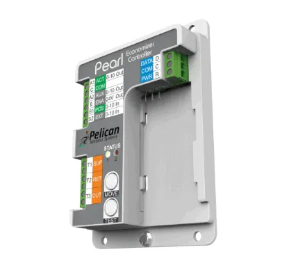
- Some economizer logic controllers (for example, a factory economizer module) manage outdoor-air dampers independently and only need a stage call from the thermostat; others expect the thermostat to provide an occupancy or
OCCsignal. - Demand-controlled ventilation may rely on a CO2 or occupancy sensor input - decide whether that lives at the thermostat, at a remote sensor, or at a separate controller.
- Confirm how the fan is driven during economizer/free-cooling so the control does not fight the economizer sequence.
Document exactly which device owns outdoor-air control before choosing the thermostat, since it determines whether you need an economizer-aware control or remote sensors.
5. Decide standalone vs. networked control
Finally, decide whether the RTU is controlled by a standalone thermostat or as part of a connected building-control system with gateways, controllers, repeaters, and remote sensors:
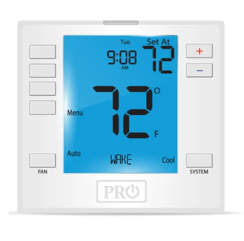
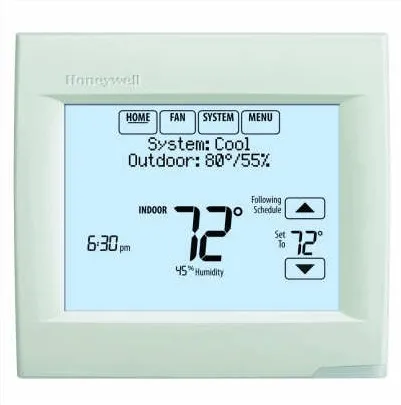
- Standalone suits a single unit with local scheduling and no remote-management requirement. Conventional commercial-grade stats from brands such as Honeywell, Resideo, or Pro1 IAQ commonly fill this role.
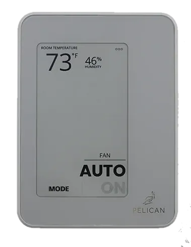
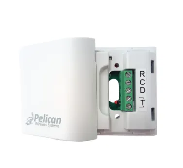
- Networked suits multi-unit sites needing central schedules, remote access, alarming, trend data, or coordination across zones. In a wireless mesh - for example, a Pelican gateway-and-repeater architecture - the wall control is only one role; the gateway, sensors, and network coverage are all part of the finished design.
If remote access, alarms, or multi-zone coordination are required, treat the project as a system selection, not a thermostat swap. See Documenting Your Existing HVAC Controls to capture the inventory, and Choosing a Commercial Thermostat for the full review process.
Verify all terminal designations against the specific unit's wiring diagram before making connections - labeling varies by manufacturer. Work should be reviewed and performed by qualified personnel in accordance with the equipment documentation and applicable codes. Information here helps organize a selection review; it does not approve an installation design or determine that a specific product is compatible with your equipment. Send your unit model, wiring photos, and required sequence to sales@coldaircentral.com for assistance.